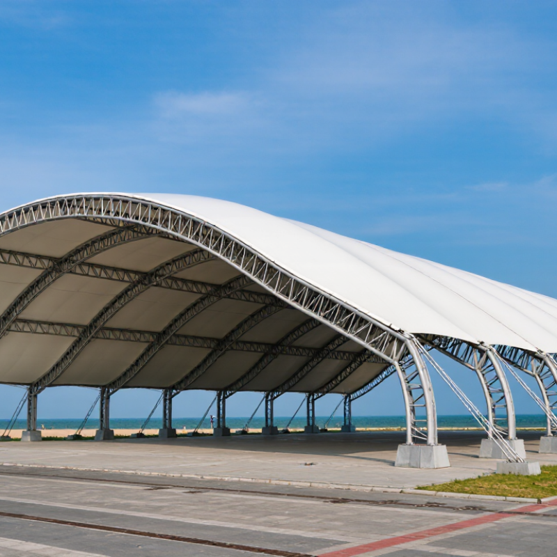
| Structural Concept | Pre-engineered frame tent, cable-net membrane, or mast-and-cable structure | Load-bearing systems typically combine steel or aluminum members with pretensioned fabric panels and edge cables. | The structural concept determines the required foundations, erection sequence, internal column arrangement, and achievable clear span. | Choose a cable-supported system when a large column-free space is the priority. |
| Typical Clear Span | Approximately 8–30 m for common temporary or semi-permanent structures | Large engineered tensile roofs can exceed this range, but span capacity depends on geometry, pretension, wind, snow, and support conditions. | Greater spans generally require stronger edge beams, higher pretension, deeper structural geometry, or additional masts and cables. | Exhibitions, sports areas, event venues, dining spaces, and covered walkways. |
| Primary Membrane Material | PVC-coated polyester, PTFE-coated fiberglass, or ETFE film | PVC-coated polyester is commonly used for economical and transportable structures; PTFE-coated fiberglass offers long-term durability; ETFE is a lightweight transparent film system. | Material selection affects translucency, weldability, fire behavior, cleaning requirements, expected service life, and project cost. | PTFE-coated fiberglass is often the strongest long-life choice for permanent structures; PVC-coated polyester is practical for relocatable tents. |
| Fabric Weight | About 650–1,500 g/m² for coated architectural fabrics | Heavier fabrics generally provide increased tear resistance and durability, but they also increase handling, detailing, and supporting-structure requirements. | The selected weight must match span, pretension, environmental loads, seam design, and installation equipment. | Medium- to large-scale structures exposed to repeated weather or frequent use. |
| Surface Form | Hypar, cone, ridge-and-valley, arch-supported, or pneumatic form | Anticlastic forms, such as hypar geometries, curve in opposite directions and help stabilize the membrane through pretension. | Form-finding software is used to establish a stable geometry before structural analysis and patterning. | Hypar and ridge-and-valley forms are effective where drainage, visual quality, and stiffness must be balanced. |
| Membrane Pretension | Typically specified by the structural engineer in both principal fabric directions | Pretension is commonly expressed in force per unit width and is often in the low single-digit kN/m range for architectural fabric systems, subject to the fabric and design code. | Insufficient pretension can cause flapping and ponding; excessive pretension can overstress seams, fittings, or supporting members. | All tensile membrane structures, especially roofs with low curvature. |
| Roof Drainage | High points, valleys, gutters, scuppers, and concealed or external downpipes | Drainage geometry must prevent water ponding under the design rainfall condition and account for membrane deflection. | Water flow paths should be resolved during form-finding rather than added after fabrication. | Essential for regions with heavy rainfall, monsoon conditions, or frequent storms. |
| Wind Design | Project-specific calculation using local wind speed, exposure, terrain, height, and importance category | Wind uplift and pressure can govern edge detailing, anchor forces, cable sizes, and foundation design. | Perimeter reinforcement and robust anchorage are especially important because membrane edges can experience high local suction. | Structures in coastal, open, elevated, or cyclone-prone locations require site-specific wind engineering. |
| Snow and Rain Load | Determined by local climate and applicable building code | Snow accumulation and ponding risk are strongly influenced by roof curvature, valley layout, insulation, heating, and drainage. | Cold-climate designs may need steeper geometry, snow-shedding details, higher pretension, or increased supporting capacity. | Permanent or seasonal structures in temperate, alpine, or high-latitude regions. |
| Fire Performance | Depends on membrane coating, substrate, assembly, and the governing code classification | Architectural fabrics are available in flame-retardant grades, but the complete roof assembly must be tested or assessed as required by local regulations. | Fire documentation should be confirmed before specification because fabric performance varies by product construction and test method. | Public venues, hospitality areas, temporary event spaces, and enclosed structures. |
| Natural Daylight | Translucency commonly ranges from low-translucency opaque fabric to highly translucent film systems | Translucent membranes can reduce daytime electric-light demand while controlling glare through color, coating, geometry, and shading. | Daylight modeling should consider solar heat gain, internal temperature, glare, and nighttime lighting appearance. | Translucent roofs are effective for atriums, markets, sports facilities, and event halls. |
| Thermal Performance | Single-layer membranes provide limited insulation; cushion or multilayer systems provide improved thermal control | Thermal performance is governed by membrane layers, air gaps, surface properties, ventilation, and the use of mechanical conditioning. | For conditioned buildings, membrane roofs often need additional insulation, an inner liner, or a separate enclosed envelope. | Seasonal venues, covered outdoor spaces, and projects where passive ventilation is acceptable. |
| Fabrication Process | Digital form-finding, patterning, CNC cutting, heat welding, edge reinforcement, and factory inspection | Fabric panels are cut from compensated patterns to account for fabric stretch, coating behavior, and the final pretensioned shape. | Accurate digital coordination between engineering, patterning, steelwork, and connection details is critical to fit-up quality. | Custom roofs with complex curvature, repeated modules, or demanding visual requirements. |
| Connection Details | Clamps, keder edges, bolted plates, ropes, webbing, corner plates, and stainless-steel fittings | Connections must transfer membrane tension without cutting, tearing, or creating concentrated stress at corners and penetrations. | Rounded transitions, reinforced corners, replaceable hardware, and inspection access improve reliability and maintenance. | All projects; detailing quality is a major determinant of service performance. |
| Foundation Requirements | Ground anchors, isolated footings, strip foundations, ballast systems, or reinforced concrete foundations | Foundation size is controlled by vertical reactions, uplift, horizontal forces, overturning, soil conditions, and temporary or permanent status. | Temporary tents may use engineered ballast or removable anchors, while permanent structures usually require site-specific geotechnical design. | Temporary installations, permanent civic structures, and structures on variable ground conditions. |
| Construction Sequence | Survey and foundations → steel or mast erection → cable installation → membrane lifting → tensioning → final inspection | Membranes should be installed under suitable weather conditions and tensioned progressively to avoid uneven loading or local overstress. | Sequencing must coordinate lifting plans, temporary supports, crane access, weather monitoring, and connection tolerances. | Projects with limited site access, tight event schedules, or complex temporary works. |
| Installation Tolerance | Project-specific; typically coordinated through surveyed support points and adjustable connection hardware | Small dimensional errors can affect membrane fit, pretension distribution, drainage, and visual symmetry. | As-built surveys and adjustable turnbuckles, clamps, or cable fittings help achieve the intended final geometry. | High-visibility roofs and structures with multiple connected membrane panels. |
| Expected Service Life | Approximately 10–20 years for many PVC-coated polyester systems; longer periods are possible for PTFE-coated fiberglass systems | Actual life depends on ultraviolet exposure, pollution, climate, cleaning, membrane movement, seam quality, and maintenance. | Service-life expectations should be based on the selected material system and the environmental exposure category rather than a generic material label. | For long-term permanent use, select a membrane and connection system with documented durability for the project climate. |
| Inspection and Maintenance | Routine visual inspections, cleaning, drainage checks, hardware checks, and post-storm assessments | Inspection commonly focuses on seams, edge cables, corner reinforcements, coating damage, corrosion, ponding, and membrane tension. | Early repair of small cuts, loose fittings, blocked drains, or corrosion can prevent more extensive damage. | All membrane structures, particularly those in industrial, coastal, dusty, or high-wind environments. |
| Best Overall Selection in 2026 | Engineered tensile membrane system matched to the site, climate, occupancy, and expected service life | No single membrane tent is universally best. The most suitable solution balances structural safety, material durability, daylight, thermal needs, installation speed, maintenance, and budget. | Use a qualified structural engineer, a form-finding and patterning workflow, code-compliant calculations, certified fabric documentation, and an installation quality plan. | For a durable permanent venue: engineered PTFE-coated fiberglass or an equivalent long-life system. For a relocatable event tent: flame-retardant PVC-coated polyester with verified wind and ballast design. |


 Your message must be between 20-3,000 characters!